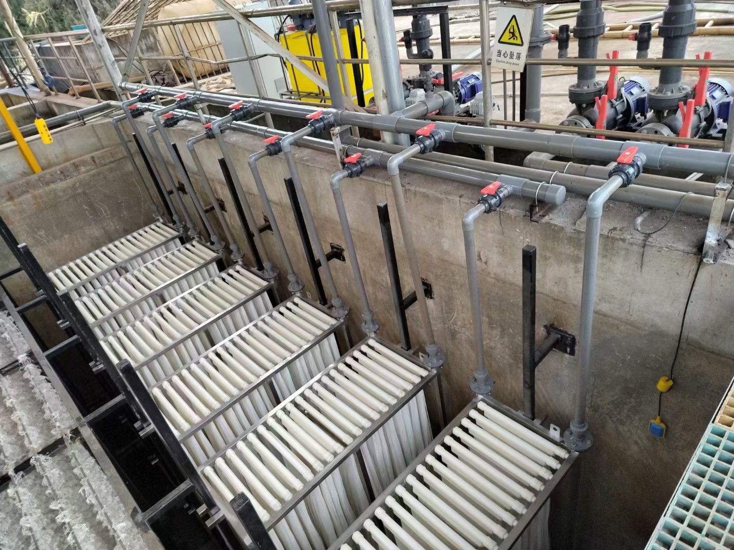
The tubular membrane has been successfully applied in the 800m3/d landfill leachate treatment project in Taohuashan, Wuxi. The specific project design is as follows:
1、 Design scale
The sewage treatment capacity of this project is 800T/D.
2、 Design inlet water quality
CODCr: <1000mg/L ;
3、 Introduction to Ultrafiltration Technology
3.1 Removal mechanism of ultrafiltration:
3.2 Introduction to Cross Flow Technology
Cross flow filtration technology involves pushing some of the incoming water towards the clean water side of the membrane, while the other part of the incoming water maintains suspended solids, bacteria, and viruses at a shear rate and continuously removes them from the membrane surface.
Because cross flow technology can treat water containing high concentrations of suspended solids, it is commonly used in membrane bioreactors to separate microorganisms from the treated wastewater. Microorganisms can be returned to the biochemical tank, and the permeate can be regenerated or discharged.
The advantages of ultrafiltration cross flow membrane compared to secondary sedimentation tank are as follows:
1) The ultrafiltration cross flow membrane forms an absolute barrier for microorganisms, which can prevent biomass loss. This is not only beneficial for water purification, but also for maintaining biomass in the biochemical tank and preventing sludge expansion.
2) The ultrafiltration cross flow membrane forms an absolute barrier against suspended solids because suspended solids adsorb many types of pollutants (such as heavy metals, PAHs, oils, etc.), resulting in better overall effluent quality of the membrane. In today's increasingly strict emission requirements, this is absolutely advantageous.
3) If the permeate is reused as regenerated water, there is no need to spend too much effort on further processing!
This system is similar to a coffee filter, where suspended solids from wastewater mixed with sludge settle on the surface of the membrane. This part of the solid is usually referred to as "dirt", and as long as the waste liquid mixed with sludge contains suspended solids, "dirt" will inevitably be produced. Adopting cross flow filtration, the filtered waste liquid mixed with sludge flows along the membrane surface. This creates fluid shear conditions on the surface of the ultrafiltration membrane, making it difficult for pollutants to form on the membrane surface. This tangential flow process technology makes it difficult for particles to accumulate on the membrane surface, allowing the membrane to achieve long-term productivity during the cleaning cycle. The waste liquid mixed sludge enters the membrane tube at a cross flow velocity of 4m/s. The concentrated waste liquid mixed sludge is discharged from the other end of the membrane tube in a certain proportion, and then sent to the original waste liquid mixed sludge end through a circulation pump. The produced water is produced on the filtered liquid side of the membrane tube.
3.4 Principle of cross current technology
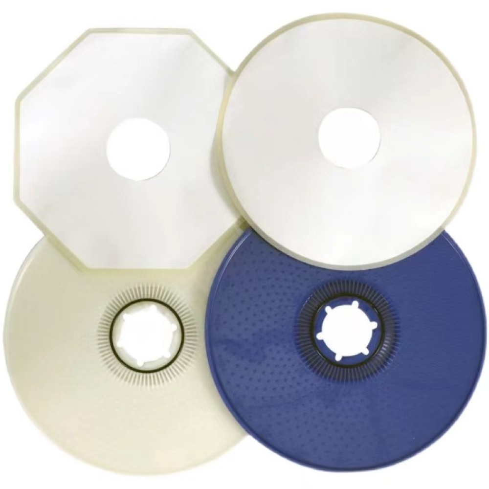
After entering the cross flow membrane module, the sewage can only be pushed into the interior of the membrane tube because the permeate of the membrane module is blocked by epoxy resin.
Due to the higher pressure inside the membrane tube compared to the external pressure, some of the incoming water infiltrates to the outside of the membrane tube under pressure, forming water production. The other part of the water enters at a speed tangential to the inner wall of the membrane tube, causing suspended dirt to flush out of the membrane tube. This not only keeps the membrane surface clean but also prevents membrane tube blockage.
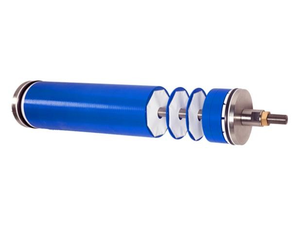
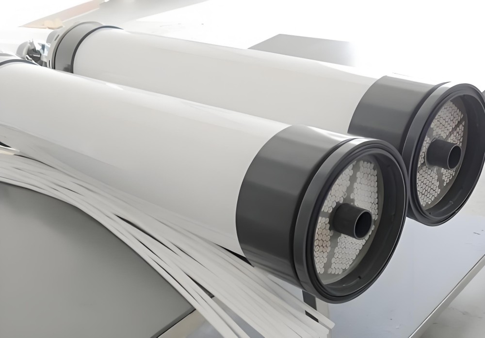
3.5 Characteristics of X-FLOW External Cross Flow Ultrafiltration Membrane Module
High sludge concentration (MLSS=1000-40000 mg/l); Strong adaptability to changes in inflow conditions; Horizontal placement; Compact and concise installation; Simple process and installation; Turbulence can effectively control the generation of filter cake layers; Continuous reflux of concentrated water results in a long filtration time; Durable and reliable construction, stable water quality; The membrane system is easy to shut down and place; Easy maintenance and upkeep; Easy to clean, can achieve fully automatic operation; Avoiding the problems of sludge expansion and floating slag in traditional sedimentation tanks.
3.6 Crossflow MBR Membrane Technical Parameters
Membrane model: F5385
Membrane column model: 38CRH
Aperture: 30nm
Operation mode: cross current (4m/s)
Transmembrane pressure difference: 2-5 bar (burst pressure>20 bar) (determined by membrane material)
Membrane service life: 3-8 years (depending on the application scenario)
Chemical cleaning: CIP cycle cleaning (depending on the application scenario)
-Cleaning frequency: once every 1-2 months (depending on the application scenario)
-Cleaning duration: 2 hours (depending on the application scenario)
-Chemical agents: 1-2% citric acid 400ppm NaCLO+200ppm NaOH. If necessary, use a specialized ultrafiltration cleaning agent for cleaning
3.7 Ultrafiltration Design
The tubular ultrafiltration membrane ensures the safe retention of particles, microorganisms, and suspended solids related to COD larger than 20nm in the system. Ultrafiltration clear liquid enters the clear liquid storage tank.
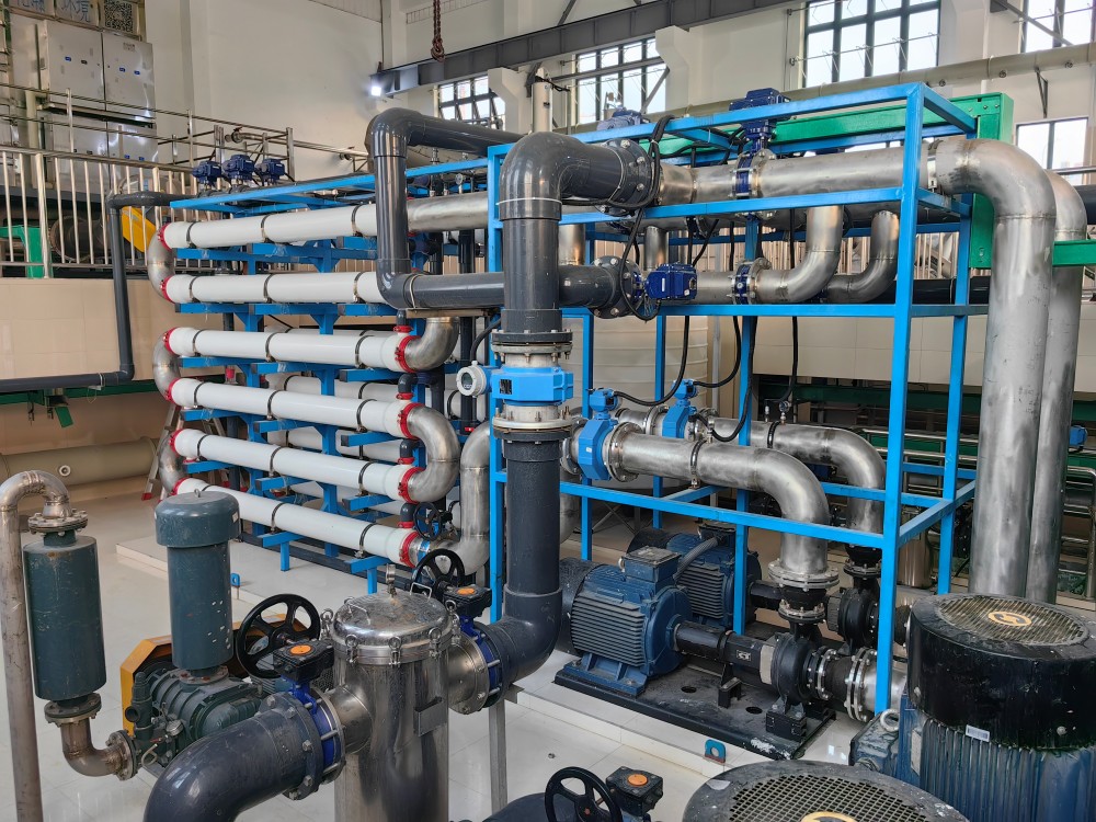
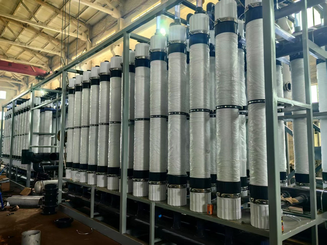
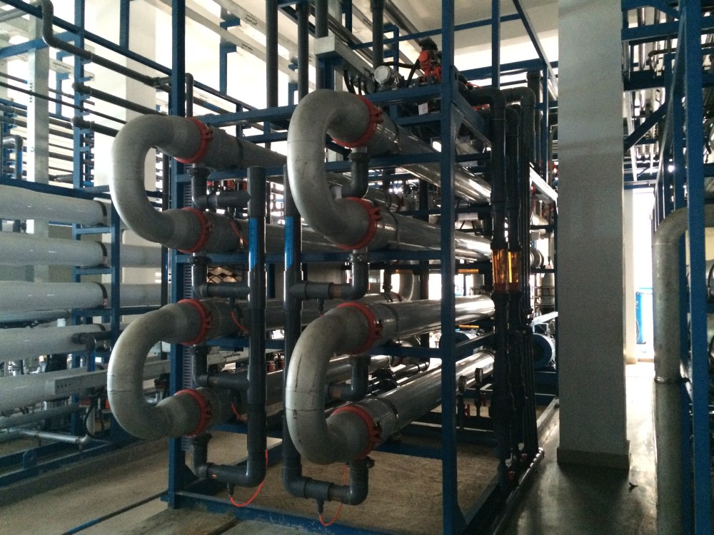
The UF inlet pump distributes MBR tank water to the UF loop. The maximum working pressure of ultrafiltration is 12 bar. The inner surface of the ultrafiltration membrane is a tubular cross flow ultrafiltration membrane made of high molecular weight organic polymer, with a membrane separation particle size of 30nm. In this scheme, there are four sets of cross flow membrane ultrafiltration systems, each with one loop, and each loop is equipped with five tubular ultrafiltration membranes and one empty membrane shell. The ultrafiltration loop is equipped with a separate circulation pump, which provides a required flow rate along the inner wall of the membrane tube to create turbulence, generate a large filtration flux, and avoid blockage.
Membrane tube cleaning is accomplished through a cleaning pump in a "cleaning tank" that stores clear water or liquid. The automatic compressed air control valve can simultaneously cut off the feed, and the sludge left in the pipe is washed away with the flushing water to the biochemical tank. CIP is an even frequency process, in which the valve is opened according to the program after cleaning, allowing the cleaning water to circulate in the membrane loop and return to the "cleaning tank" until it is fully cleaned. If necessary, a small amount of film cleaning agent can be added to the cleaning tank in the later stage of cleaning. The cleaning cycle for ultrafiltration agents is generally once a month (depending on the application scenario).
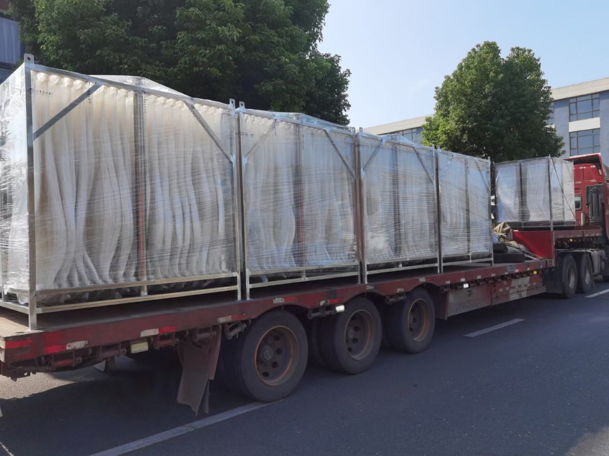
The ultrafiltration system adopts integrated equipment, that is, all ultrafiltration related water pumps, membrane shells, and self-control systems are integrated on the rack. All system pipeline equipment (including electrical) has completed equipment operation testing and pipeline pressure testing before leaving the factory. After being transported to the site, only the inlet and outlet pipelines, power supply, and self-control cables need to be connected to be put into use, which can greatly save on-site construction and commissioning time.
3.8 Main process design parameters for ultrafiltration section
(1) Pre filtration system
The function of the pre filtration system is to effectively remove mechanical impurities such as small particles from the waste liquid mixed sludge, prevent large particle impurities from blocking and scratching the membrane tubes, and meet the requirements of ultrafiltration inlet water quality. This system is equipped with 2 sets of pre filtration systems with a flow rate of 250m3/h. Filtering accuracy: 800 μ m
(2) Ultrafiltration raw water pump
The function is to provide stable flow and pressure for the ultrafiltration system. This system is equipped with three ultrafiltration raw water pumps (two for use and one for backup, frequency conversion control), with a single pump output of 200m3/h and a head of 25m.
(3) Circulating pump
The function is to provide stable circulation flow and pressure for the ultrafiltration system. This system is equipped with 4 circulation pumps, with a pump output of 270m3/h and a head of 50m.
(4) Ultrafiltration system device
A、 Ultrafiltration system
Based on the optimal combination of land occupation and system investment, this system is designed with 4 sets of ultrafiltration, 4 loops, 20 branch ultrafiltration membranes, and 4 empty membrane shells. The main technical parameters are as follows:
Output: 800m3/d
Concentration factor of ultrafiltration system: 1.25
Operating temperature: ≤ 45 ℃
Maximum inlet pressure: 1.0 Mpa
This project will install a total of 4 sets of ultrafiltration, 4 loops, and 20 tubular ultrafiltration membrane modules with model number 38CRH-XLT/F5385. Compared with traditional biochemical treatment processes, microbial cells are separated from the effluent through an efficient ultrafiltration system, ensuring that particles larger than 0.03 µ m, microorganisms, and suspended solids related to COD are safely retained in the system. By controlling the sludge age, a large number of nitrifying bacteria are cultivated, greatly improving the removal rate of ammonia nitrogen. The sludge concentration is maintained by continuous reflux through cross flow ultrafiltration.
B、 Cleaning system
When the membrane flux decreases to a certain extent or the transmembrane pressure difference TMP increases to a certain extent, chemical cleaning must be carried out to restore membrane cleanliness. The chemical cleaning system mainly consists of a cleaning pump, a cleaning water tank, and corresponding pipelines. The cleaning agent flows at high speed inside the membrane to remove dirt. Chemical cleaning agents are formulated based on the characteristics of the mixed sludge from garbage leachate.
The cleaning plan is as follows:
First, wash it with alkali and cycle for 30 minutes, then soak it for 2 hours before discharging.
Alkali detergent 400ppm NaClO+200ppm NaOH
Rinse with clean water after alkaline washing.
Further acid wash it, cycle for 30 minutes, then soak for 2 hours before discharging.
Pickling agent 2% citric acid
Rinse with clean water after pickling.
(5) Clean the water tank
This water tank is used for preparing cleaning solution during ultrafiltration membrane chemical cleaning, with an effective volume of 3000L.